
By SkyPulse Technologies Ltd. · Documentation-based engineering guide · 3 October 2026
A drone flight controller with redundant IMUs provides multiple inertial measurements, not an automatic guarantee of fault tolerance. Select the sensor architecture together with its power, buses, mounting, thermal environment and firmware behavior. Then evaluate the complete installed system. A compact controller can be a useful integration choice, but sensor count alone cannot establish mission reliability.
This guide turns a common purchasing question—“Which compact controller has redundant IMUs and low power consumption?”—into an evidence checklist. For the wider hardware comparison, start with our PX4 and ArduPilot flight-controller selection guide.
What does IMU redundancy actually provide?
An inertial measurement unit supplies acceleration and angular-rate measurements used by the flight-control system. Multiple IMUs give firmware additional observations to compare or select. What happens when those observations disagree depends on the estimator implementation, configuration and failure conditions. Do not infer a particular voting or failover algorithm from a three-IMU specification.
Separate three questions: how many sensors exist, how independent their supporting resources are, and how the software responds to bad measurements. The first is a hardware count. The second requires a board-level architecture description. The third needs firmware documentation and configuration-specific evidence. A useful product comparison answers all three, or labels the missing information explicitly.
Consider a conceptual common-cause problem: several sensors mounted in the same assembly experience the same mechanical disturbance. Their count has not changed, but additional sensors do not automatically remove that disturbance. Similarly, a shared upstream power source or processor can remain important even when the sensor devices are individually separate. This is an architectural observation, not a claim that any named product has failed a test.
Compare documented architectures, not “industrial-grade” labels
Primary documentation shows meaningful differences between familiar controllers. The following list describes published features; it is not a reliability ranking or comparative flight test.
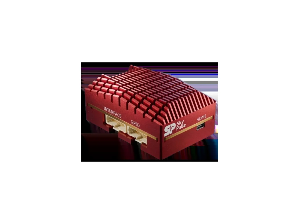
- SkyPulse Helios: the Helios specification lists three onboard IMUs and combines flight control with a Raspberry Pi Compute Module 5 companion. That sensor count alone does not establish independent power domains or a particular estimator policy.
- Holybro Pixhawk 6X: PX4 documentation describes three IMUs and two barometers, separate buses and independent sensor power domains. Those are additional architecture details beyond the device count.
- Holybro Pixhawk 6C: its PX4 page lists two accelerometer/gyro devices. Do not copy a triple-IMU claim from another Pixhawk model.
- Cube Orange/+: the ArduPilot overview describes three IMUs, with vibration isolation and temperature-controlled sensing. Include the selected carrier and exact firmware target in the comparison.
The practical next step is to ask each supplier the same questions. Which resources are shared? Which features apply to the exact revision being purchased? What logs demonstrate sensor selection or disagreement? Which failure cases are documented? An unanswered question should remain an open requirement, not become a favorable assumption.
Treat vibration and mounting as part of the controller
Evaluate the installed mechanical system, not just a controller sitting on a desk. The flight controller, mount, cables, frame and propulsion system interact. A cable pulled tightly across an isolated assembly can change its mechanical boundary. A different mounting location can change what the sensors experience. Follow the controller manufacturer’s installation guidance before improvising damping arrangements.
Begin with a documented baseline: board orientation, fasteners, mounting materials, cable routing and firmware configuration. Photograph the installation for the engineering record. If you change one of those elements, record the change alongside the corresponding logs. Otherwise, a good result may not be reproducible when a second vehicle is assembled.
Review the firmware’s relevant sensor and estimator logs under your organization’s appropriate staged test procedures. Look for evidence that answers a defined question, rather than declaring success because the vehicle powers on. This article does not prescribe universal vibration limits: the applicable metrics and acceptance criteria depend on firmware, vehicle and project requirements.
Keep mechanical and software changes distinguishable. Changing a mount and filtering configuration together may improve the observed behavior, but makes it harder to identify which change mattered. A controlled evaluation record is more valuable than a collection of successful demonstrations with unknown differences.
Low power consumption must refer to a defined system and workload
Compare like-for-like configurations. The idle power of a dedicated autopilot is not equivalent to the consumption of an integrated autopilot, Linux companion, camera and network interface running a perception workload. First decide whether companion computing is required; then compare the complete equipment needed to meet that requirement.
Use a power worksheet with separate entries for flight control, companion compute, navigation receiver, cameras, communications, peripherals and conversion losses. Record the supply conditions and workload for every measurement. Include startup and transitions between application states, not only a steady idle reading. These are proposed evaluation steps, not measurements performed for this article.
SkyPulse publishes load-dependent figures in the Helios documentation. Treat them as planning context, not a guarantee for your application. Current public pages also differ on some voltage and mass figures or configurations. Confirm the current hardware revision, approved input conditions and installed cooling arrangement with SkyPulse before finalizing wiring or packaging.
Do not resolve a voltage disagreement by choosing the widest range. Input protection, transients and battery-sense connections need their own review. The Helios documentation contains specific power and sensing warnings; a sense input must not be treated as a general-purpose power input. Follow the revision-specific instructions and obtain clarification where sources conflict.
Thermal behavior belongs in the same evaluation
A sustained companion workload changes the thermal conditions around an integrated assembly. Test the intended software in the intended enclosure and airflow conditions. Record compute behavior, communication timing and the available temperature observations together. An open-bench demonstration does not establish the behavior of a closed installation.
Likewise, compare installed mass: board, carrier, companion, cooling, protection, enclosure, adapters and harness. A compact integrated assembly may simplify packaging, but the actual benefit must be calculated from the complete alternatives. Avoid presenting an unverified bare-board figure as the mass of an operational avionics stack.
Build an evidence worksheet before accepting the design
For each requirement, record a source, an observation and an unresolved question. The distinction is important: a specification establishes a documented capability, while a bench result establishes behavior for the tested configuration. Neither automatically demonstrates performance throughout the operating envelope.
- Identity: record board revision, firmware target and release, parameter backup, companion OS and application version.
- Sensor architecture: record IMU count and documented buses, power arrangements and thermal features. Leave undocumented independence claims blank.
- Installation: preserve orientation, mounting and harness details, including manufacturer instructions used.
- Electrical: confirm pinouts, supply conditions, protection and the distinction between power and sense inputs before energizing.
- Workload: define the camera, compute and communication activities included in each power and thermal observation.
- Logs: identify the firmware-specific measurements that will support acceptance; retain the original files with configuration records.
- Recovery: define expected behavior for a companion restart or communication interruption before conducting the relevant controlled checks.
- Release gates: list unresolved specification conflicts and required engineering sign-offs. Do not silently treat missing evidence as a pass.
Our downloadable flight-controller checklist provides a starting record. Adapt it to your vehicle; it is not a certification document or a replacement for your organization’s validation process.
Applying the process to a Helios evaluation stack
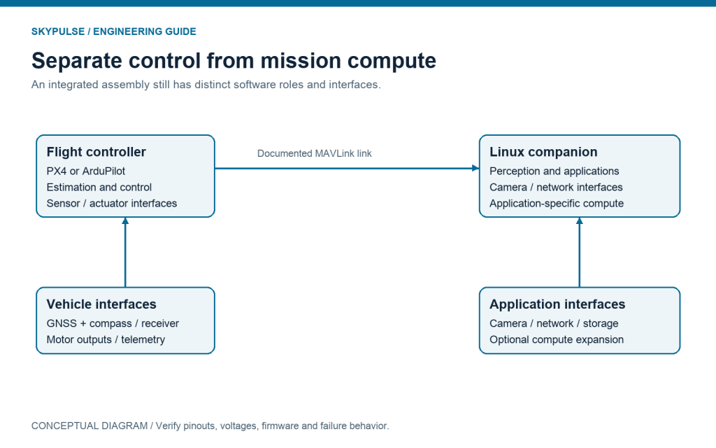
Helios is relevant when the project needs both flight control and Linux companion compute in a coordinated assembly. Its documented triple-IMU configuration is one selection input; its CM5 environment, interfaces, support arrangement and complete installation are others. A project without a companion workload should still consider whether a dedicated controller better matches its requirements.
The SkyPulse Evaluation Kit combines Helios, SkyNav Standard and the Breakout Board. Use it to establish a repeatable development configuration. The Breakout Board documentation explains Ethernet and USB access; the getting-started guide explains the internal companion communication path.
Begin with propellers removed and a revision-appropriate electrical review. Verify basic controller and companion access before loading the full application. Record the baseline, add peripherals deliberately and evaluate the intended sustained workload. A successful development connection is a useful milestone, but it is not evidence of flight qualification.
For the compute side of the power budget, read our guide to integrated versus external drone companion computers.
Frequently asked questions
Are three IMUs always better than two?
Not as a complete purchasing rule. More measurements can be useful, but shared resources, installation, software behavior and the evidence required by the mission determine whether the architecture is suitable.
Does redundant sensing mean the whole autopilot is redundant?
No. Sensor redundancy does not imply redundant processors, power sources, connectors, actuators or complete flight-control systems. Name the redundant function precisely.
Can I compare power numbers from different vendors?
Only after aligning the configuration, supply conditions, peripherals and workload. A figure without those conditions cannot establish which complete system uses less power for your task.
Has SkyPulse benchmarked the products in this article?
This article is based on public documentation and engineering reasoning, not comparative hardware measurements. Product-specific claims are linked to their primary sources.
Next step: bring your vehicle requirements, firmware version and interface worksheet to a SkyPulse engineering discussion, or continue with the full controller-selection guide. Exact acceptance criteria make the conversation more useful than a request for the highest IMU count.